dienelectrics@gmail.com
 0909186879 dienelectrics@gmail.com

Technical Data
|
|
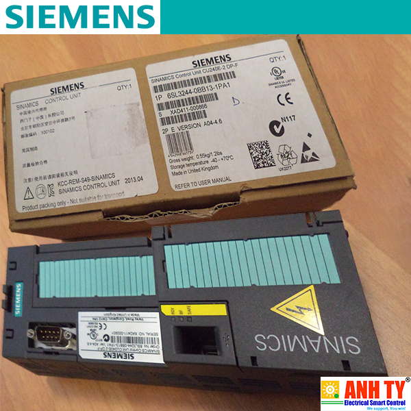
CU240E-2 |
CU240E-2 F |
|---|---|---|
|
Digital inputs |
6 |
6 |
|
Fail-safe |
1 |
3 |
|
Digital outputs |
3 |
3 |
|
Analog inputs |
2 |
2 |
|
Analog outputs |
2 |
2 |
|
MMC/SD card slot |
Yes |
Yes |
|
Motor temperature sensors |
PTC/KTY |
PTC/KTY |
|
Communication |
RS485/USS |
RS485/USS |
|
Safety Integrated |
STO |
STO, SS1, |
Technical Data
|
CU240E-2 ... |
DP |
DP-F |
PN |
PN-F |
|---|---|---|---|---|
|
Digital inputs |
6 |
6 |
6 |
6 |
|
Fail-safe |
1 |
3 |
1 |
3 |
|
Digital outputs |
3 |
3 |
3 |
3 |
|
Analog inputs |
2 |
2 |
2 |
2 |
|
Analog outputs |
2 |
2 |
2 |
2 |
|
MMC/SD card slot |
Yes |
Yes |
Yes |
Yes |
|
Motor temperature sensors |
PTC/KTY |
PTC/KTY |
PTC/KTY |
PTC/KTY |
|
Communication |
PROFIBUS |
PROFIBUS |
PROFINET |
PROFINET |
|
Profiles |
PROFIdrive |
PROFIdrive |
PROFIdrive |
PROFIdrive |
|
Safety Integrated |
STO |
STO, SS1, |
STO |
STO, SS1, |

The specific Control Unit (CU250S-2) is particularly suited for drives with high requirements in speed and torque accuracy. The I/O interface, the fieldbus interfaces and additional software functions optimally support these applications.
Technical Data
|
CU250S-2 ... |
USS |
DP |
PN |
CAN |
|---|---|---|---|---|
|
Digital inputs |
11 |
11 |
11 |
11 |
|
Fail-safe |
3 |
3 |
3 |
3 |
|
Digital in-/outputs |
4 |
4 |
4 |
4 |
|
Analog inputs |
2 |
2 |
2 |
2 |
|
Analog outputs |
2 |
2 |
2 |
2 |
|
Encoder |
Resolver, TTL/HTL Encoder, |
SIN/COS Encoder, |
||
|
MMC/SD card slot |
Ja |
Ja |
Ja |
Ja |
|
Motor temperature sensors |
PTC/KTY |
PTC/KTY |
PTC/KTY |
PTC/KTY |
|
Communication |
USS/Modbus RTU |
PROFIBUS |
PROFINET |
CANopen |
|
Profiles |
- |
PROFIdrive |
PROFIdrive |
- |
|
Safety Integrated |
|
|
||
|
Basic |
STO, SS1, SBC |
|
||
|
Advanced |
SLS, SDI, SSM |
|
||

The specific control unit (CU230P-2) is ideal for the use with drives with integrated technology functions for pump, fan and compressor applications. The I/O interface, the fieldbus interfaces and the additional software functions optimally support these applications.
Technical Data
|
CU230P-2 ... |
HVAC |
DP |
PN |
|---|---|---|---|
|
Digital inputs |
6 |
6 |
6 |
|
Digital outputs |
3 |
3 |
3 |
|
Analog inputs |
4 |
4 |
4 |
|
Analog outputs |
2 |
2 |
2 |
|
MMC/SD card Slot |
Yes |
Yes |
Yes |
|
Motor temperature sensors |
PTC/KTY |
PTC/KTY |
PTC/KTY |
|
Communication |
RS485/USS, |
PROFIBUS |
PROFINET |
|
Profiles |
- |
PROFIdrive |
PROFIdrive |


|
Terminal No. |
Signal |
Features |
|---|---|---|
|
Digital inputs (DI) – Standard |
||
|
69 |
DI COM |
Reference potential for digital inputs |
|
5 ... 8, |
DI0 … DI5 |
Freely programmable |
|
Digital outputs (DO) |
||
|
18 |
DO0, NC |
Relay output 1 |
|
19 |
DO0, NO |
Relay output 1 |
|
20 |
DO0, COM |
Relay output 1 |
|
21 |
DO1, NO |
Relay output 2 |
|
22 |
DO1, COM |
Relay output 2 |
|
23 |
DO2, NC |
Relay output 3 |
|
24 |
DO2, NO |
Relay output 3 |
|
25 |
DO2, COM |
Relay output 3 |
|
Analog inputs (AI) |
||
|
3 |
AI0+ |
Differential input, switchable between current, voltage |
|
4 |
AI0- |
|
|
10 |
AI1+ |
Differential input, switchable between current, voltage |
|
11 |
AI1- |
|
|
50 |
AI2+ |
Non-isolated input, switchable between current and temperature sensors, type Pt1000/LG-Ni1000 |
|
51 |
GND |
Reference potential of the AI2/internal electronics ground |
|
52 |
AI3+ |
Non-isolated input for temperature sensors, type Pt1000/LG‑Ni1000 |
|
53 |
GND |
Reference potential of the AI3/internal electronics ground |
|
Analog outputs (AO) |
||
|
12 |
AO0+ |
Non-isolated output |
|
13 |
GND |
Reference potential of the AO0/internal electronics ground |
|
26 |
AO1+ |
Non-isolated output |
|
27 |
GND |
Reference potential of the AO1/internal electronics ground |
|
PTC/KTY interface |
||
|
14 |
T1 MOTOR |
Positive input for motor temperature sensor |
|
15 |
T2 MOTOR |
Negative input for motor temperature sensor |
|
Power supply |
||
|
9 |
+24 V OUT |
Power supply output |
|
28 |
GND |
Reference potential of the power supply/internal electronics ground |
|
1 |
+10 V OUT |
Power supply output |
|
2 |
GND |
Reference potential of the power supply/internal electronics ground |
|
31 |
+24 V IN |
Power supply input |
|
32 |
GND IN |
Reference potential of the power supply input |
|
35 |
+10 V OUT |
Power supply output |
|
36 |
GND |
Reference potential of the power supply/internal electronics ground |

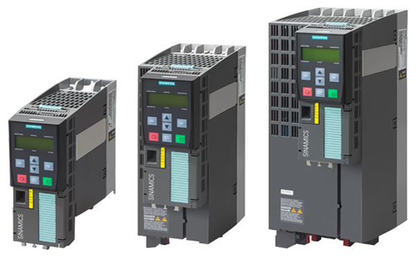
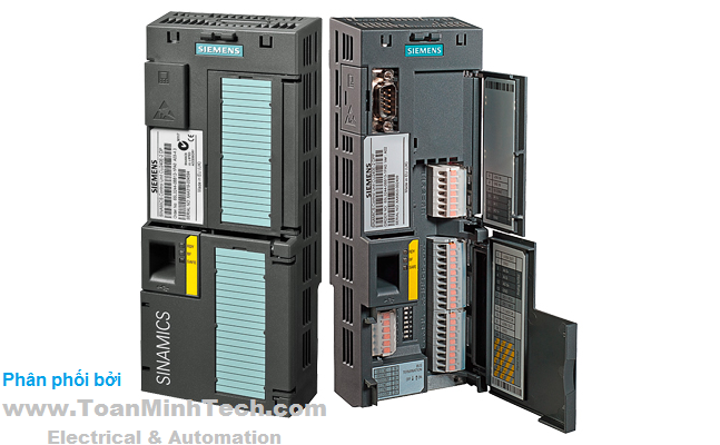
CU240E‑2 Control Unit with open and closed terminal covers
|
Terminal No. |
Signal |
Features |
|---|---|---|
|
Digital inputs (DI) – Standard |
||
|
5 ... 8, |
DI0 … DI5 |
Freely programmable (isolated) 5.5 mA/24 V |
|
69 |
DI COM1 |
Reference potential for digital inputs |
|
34 |
DI COM2 |
Reference potential for digital inputs |
|
Digital inputs (DI) – Fail-safe |
||
|
16, 17 |
F-DI0 |
Fail-safe digital inputs, 2 channels (redundant), |
|
The following are only available for CU240E‑2 F, CU240E‑2 DP‑F and CU240E‑2 PN‑F |
||
|
5, 6 |
F-DI0 |
Fail-safe digital inputs, 2 channels (redundant), |
|
7, 8 |
F-DI1 |
Fail-safe digital inputs, 2 channels (redundant), |
|
16, 17 |
F-DI2 |
Fail-safe digital inputs, 2 channels (redundant), |
|
Digital outputs (DO) |
||
|
18 |
DO0, NC |
Relay output DO0 |
|
19 |
DO0, NO |
Relay output DO0 |
|
20 |
DO0, COM |
Relay output DO0 |
|
21 |
DO1+ |
Transistor output DO1 |
|
22 |
DO1- |
Transistor output DO1 |
|
23 |
DO2, NC |
Relay output DO2 |
|
24 |
DO2, NO |
Relay output DO2 |
|
25 |
DO2, COM |
Relay output DO2 |
|
Analog inputs (AI) |
||
|
3 |
AI0+ |
Differential input, switchable between current, voltage |
|
4 |
AI0- |
|
|
10 |
AI1+ |
Differential input, switchable between current, voltage |
|
11 |
AI1- |
|
|
Analog outputs (AO) |
||
|
12 |
AO0+ |
Non-isolated output |
|
13 |
GND |
Reference potential of the AO0/internal electronics ground |
|
26 |
AO1+ |
Non-isolated output |
|
27 |
GND |
Reference potential of the AO1/internal electronics ground |
|
PTC/KTY interface |
||
|
14 |
T1 MOTOR |
Positive input for motor temperature sensor |
|
15 |
T2 MOTOR |
Negative input for motor temperature sensor |
|
Power supply |
||
|
9 |
+24 V OUT |
Power supply output |
|
28 |
GND |
Reference potential of the power supply/internal electronics ground |
|
1 |
+10 V OUT |
Power supply output |
|
2 |
GND |
Reference potential of the power supply/internal electronics ground |
|
31 |
+24 V IN |
Power supply input |
|
32 |
GND IN |
Reference potential of the power supply input |